
CNC machining basics: milling, turning, 3/4/5-axis
How the main CNC routes differ and when each is the practical choice.
Sourcing Repository guide
A practical precision CNC machining guide for engineers and procurement teams: processes, materials, tolerances, cost drivers and supplier checks, with the drawing details that decide whether a quote is comparable.
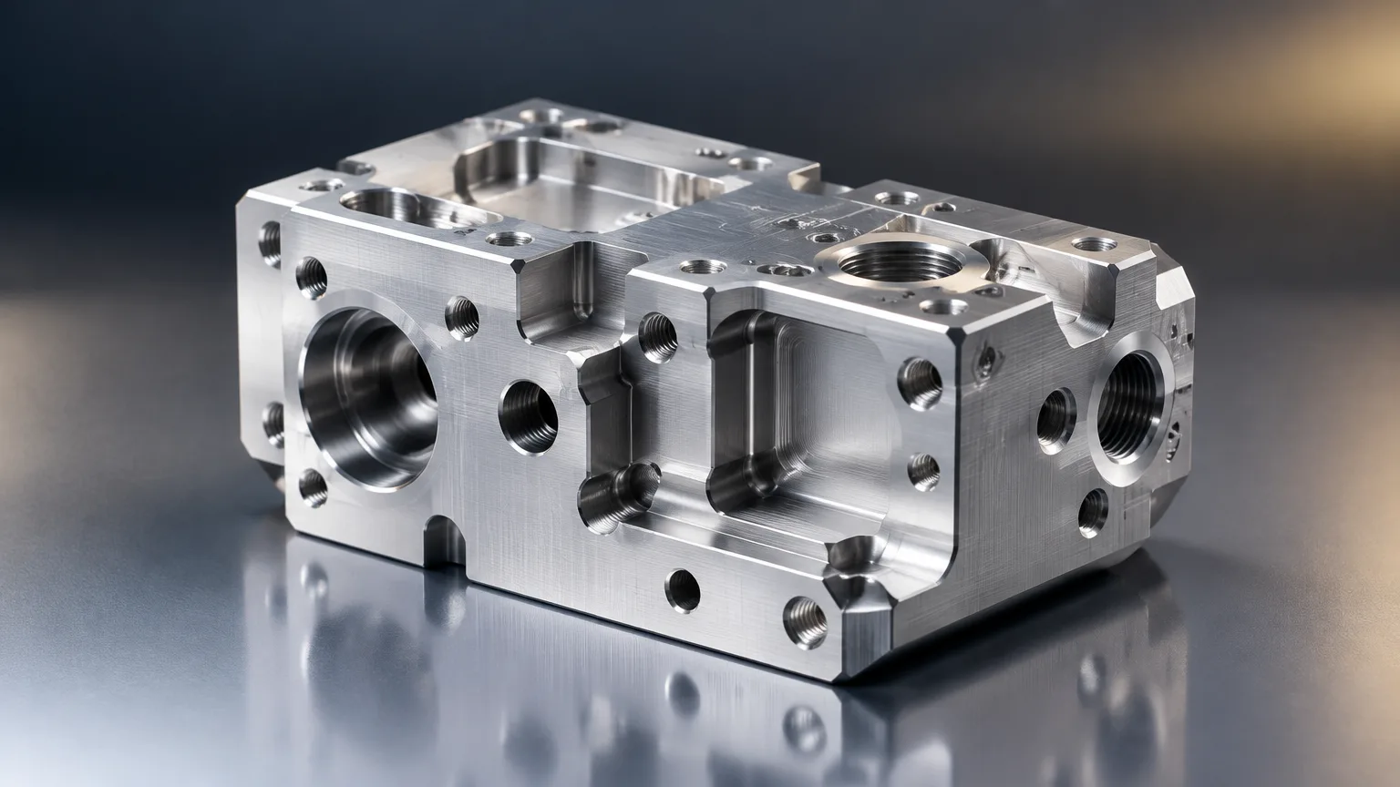
How the main CNC routes differ and when each is the practical choice.
Grades, properties and typical uses for common metals and plastics.
How to state dimensional, geometric and finish requirements clearly.
Geometry and feature choices that reduce setups, tooling and inspection.
What changes between prototype builds and production runs.
Traceability, inspection records and standard-driven requirements.
Browse the full Sourcing Repository resource library.
Start an RFQ with Sourcing Repository.
Precision CNC machining is computer-controlled material removal by milling, turning, drilling or related processes, where accuracy is defined on the drawing rather than assumed. This precision CNC machining guide covers process selection, materials, tolerances, cost drivers and supplier checks, so buyers can issue a complete RFQ and compare quotes on equal terms.
This precision CNC machining guide is written for engineers, procurement managers and founders who buy custom machined parts, with automotive work as the first reference case. It explains how precision CNC machining is defined, which process suits which geometry, how materials and tolerances are specified, what drives cost, and how to compare suppliers before an order is placed.
Precision CNC machining is computer-controlled removal of material from a workpiece using milling, turning, drilling, or related processes. Precision is achieved through controlled programming, fixturing, tooling, temperature management, and inspection; required accuracy must be defined on the drawing rather than assumed.
A precision CNC machining guide is a reference that explains how to specify, source and inspect machined parts to defined tolerances. This precision CNC machining guide covers processes, materials, tolerances, cost drivers and supplier selection so buyers can write clear drawings and compare quotes on the same basis.
For automotive programs, the drawing is the contract. A controlled CAD file and drawing should state material, grade, tolerances, datums, finish, threads, quantity and inspection requirements, because every supplier quotes only what is written down.
Reported tolerance ranges in this precision CNC machining guide are supplier references, not guaranteed universal capability. Material grades and properties should be checked against the applicable ASTM, EN or producer datasheet before release.
Use the chapter map to jump straight to the decision you are making. Each chapter of this precision CNC machining guide stands alone, but the sequence follows a normal sourcing flow: define the process, fix the material, set tolerances, estimate cost, then qualify the supplier.
The related chapters are listed again at the end of this page, together with the guides hub and the quote request route.
CNC machining processes are chosen by geometry first: rotational parts usually go to turning, prismatic and contoured parts to milling, and mixed-feature parts to mill-turn. The table below summarizes the main routes, their strengths and their practical limits.
| Route | Strengths | Limits |
|---|---|---|
| CNC milling | Suitable for prismatic parts, pockets, contours, holes, and multi-axis features. | Requires workholding access; deep cavities and thin walls increase cost and distortion risk. |
| CNC turning | Efficient for rotational parts such as shafts, bushings, and threaded components. | Less suitable for non-rotational geometry; long slender parts may deflect. |
| Mill-turn machining | Combines turning and milling with fewer setups and improved feature alignment. | Machine and programming costs are generally higher. |
| CNC drilling and tapping | Fast production of standardized holes and threads. | Hole location, chip evacuation, and deep-hole access can limit capability. |
| Wire EDM | Can produce narrow slots and hard-material features with typical reported capability of about ±0.0002–0.0004 in (±0.005–0.010 mm). | Requires electrically conductive material and is generally slower than milling. |
Milling suits prismatic and contoured parts; turning suits rotational parts and can be more efficient for shafts and bushings. Where a part has both rotational and prismatic features, mill-turn can reduce the number of setups and improve alignment between features.
Supplier capability references give a feel for the difference. General milling features are typically about ±0.002–0.004 in (±0.05–0.10 mm), and general turning is typically about ±0.001–0.002 in (±0.025–0.05 mm). These are not universal standards, so confirm them for the specific feature.
Precision work uses tighter feature requirements, more controlled setups, specialized inspection, and potentially slower feeds and additional finishing passes. That difference is a planning input, not a marketing label: it changes cycle time, fixturing and inspection effort.
Tight milled features are typically about ±0.0004–0.0010 in (±0.01–0.025 mm), and precision turning is typically about ±0.0002–0.0004 in (±0.005–0.01 mm). Any precision CNC machining guide should treat these as supplier references that depend on geometry, material and inspection.
Material choice sets machinability, strength, corrosion behavior and inspection needs. The table gives common grades and typical uses; verify material identity, grade, condition, and certificates with the supplier, and confirm properties against the applicable ASTM, EN, or producer datasheet.
| Material | Grade | Properties | Typical uses |
|---|---|---|---|
| Aluminum | 6061-T6 | Lightweight, corrosion-resistant, and generally machinable. | Brackets, housings, prototypes, fixtures, and aerospace parts. |
| Stainless steel | 304 | Corrosion resistance, toughness, and broad availability; work-hardening can increase machining difficulty. | Food, chemical, medical, and general industrial components. |
| Stainless steel | 316 | Improved corrosion resistance relative to 304, especially in chloride environments. | Marine, chemical-processing, medical, and sanitary hardware. |
| Carbon steel | AISI 4140 | Strength and toughness; machinability varies with heat treatment. | Shafts, tooling, fixtures, and mechanically loaded parts. |
| Engineering plastic | POM/Delrin | Low friction, dimensional stability, and good machinability. | Bushings, wear parts, guides, and electrical-mechanical components. |
Metal and plastic differ in stiffness, thermal expansion, cutting behavior, workholding, tool selection, and dimensional response. A tolerance that is routine in aluminum may be difficult in a flexible plastic, so supplier-specific limits must be verified for the exact grade.
Core design rules are simple: state every requirement on the drawing, keep tolerances only as tight as the function needs, and design for tool and workholding access. Unstated requirements become assumptions, and assumptions are where disputes start.
| Parameter | Typical range | Standard or source |
|---|---|---|
| General CNC dimensional tolerance | ±0.005 in (±0.13 mm) | Reported common/default range; verify with the supplier and drawing. |
| CNC milling, general features | ±0.002–0.004 in (±0.05–0.10 mm) | Supplier capability reference; not a universal standard. |
| CNC milling, tight features | ±0.0004–0.0010 in (±0.01–0.025 mm) | Supplier capability reference; depends on geometry, material, and inspection. |
| CNC turning, general | ±0.001–0.002 in (±0.025–0.05 mm) | Supplier capability reference. |
| CNC turning, precision | ±0.0002–0.0004 in (±0.005–0.01 mm) | Supplier capability reference; must be confirmed for the feature. |
| General unspecified tolerances | ISO 2768-f, -m, -c, or -v classes | ISO 2768 designation; class and applicable part must appear on the drawing. |
| Geometric tolerancing | Feature-specific; no single universal range | ASME Y14.5 or ISO 1101, as specified by the drawing. |
Deep cavities and thin walls increase cost and distortion risk because they limit workholding access and tool rigidity. Long slender turned parts may deflect. Hole location, chip evacuation, and deep-hole access can limit drilling capability, so review these features before finalizing tolerances.
Cost is driven by time and risk: programming and setup, machine time, tooling, fixturing, finishing and inspection. Tolerance is the largest single lever, because tighter limits can require slower cutting, extra passes, controlled environments, and more inspection.
Relax noncritical tolerances, simplify setups, use standard tools and threads, avoid deep cavities, select machinable materials, and consolidate compatible features. These changes reduce cycle time and inspection burden without weakening the function of the part.
The most useful habit from this precision CNC machining guide is to tighten only the features that control fit or function. Everything else can stay at the general tolerance class stated on the drawing.
A CNC machining supplier checklist should compare verified process capability, material traceability, inspection equipment, certifications, capacity, lead time, corrective-action practice, and comparable sample work. A supplier that cannot show evidence for a claim should not be scored on that claim.
Send the same controlled drawing, revision, quantity and inspection requirement to every supplier. Then compare on scope, not headline price: a quote that excludes finishing, inspection or documentation is not the same offer as one that includes them.
This precision CNC machining guide recommends scoring each supplier against the checklist above and recording the evidence behind each score. Specific supplier capabilities, certifications, capacity and pricing must be verified for each quote.
A complete RFQ is the fastest route to comparable quotes. Provide a native or neutral CAD file plus a controlled drawing specifying material, grade, tolerances, datums, finish, threads, quantity, and inspection requirements.
Upload it with quantity and material to start a quote.
FAQ
Tighter tolerances can require slower cutting, extra passes, controlled environments, and more inspection. One supplier reports non-linear cost increases below ±0.005 in (±0.13 mm), so cost can rise sharply rather than gradually as limits tighten.
Relax noncritical tolerances, simplify setups, use standard tools and threads, avoid deep cavities, select machinable materials, and consolidate compatible features. Each change reduces cycle time, fixturing or inspection effort, which is where most of the cost sits.
Provide a native or neutral CAD file plus a controlled drawing specifying material, grade, tolerances, datums, finish, threads, quantity, and inspection requirements. Include the drawing revision so every supplier quotes the same configuration.
A commonly reported default is ±0.005 in (±0.13 mm), but actual capability depends on process, material, geometry, and supplier equipment. Confirm the achievable range for the specific feature before releasing the drawing.
Related resources
Ready when you are
Send your CAD files and controlled drawing to Sourcing Repository. SR collects quotes from a vetted supplier network, manages quality and inspection, and delivers parts. Typical quote turnaround is 5-7 working days.
Your files stay confidential. NDA available on request.