
Prototype CNC Machining
Prototype Machining for CNC Machined Prototypes
Prototype machining produces one-off and low-volume CNC prototypes in metal and plastic so you can test fit, form and function before committing to production tooling.
- Metal and plastic
- ±0.005 in general tolerance
- 1 to 100+ pieces
- Inspection reports
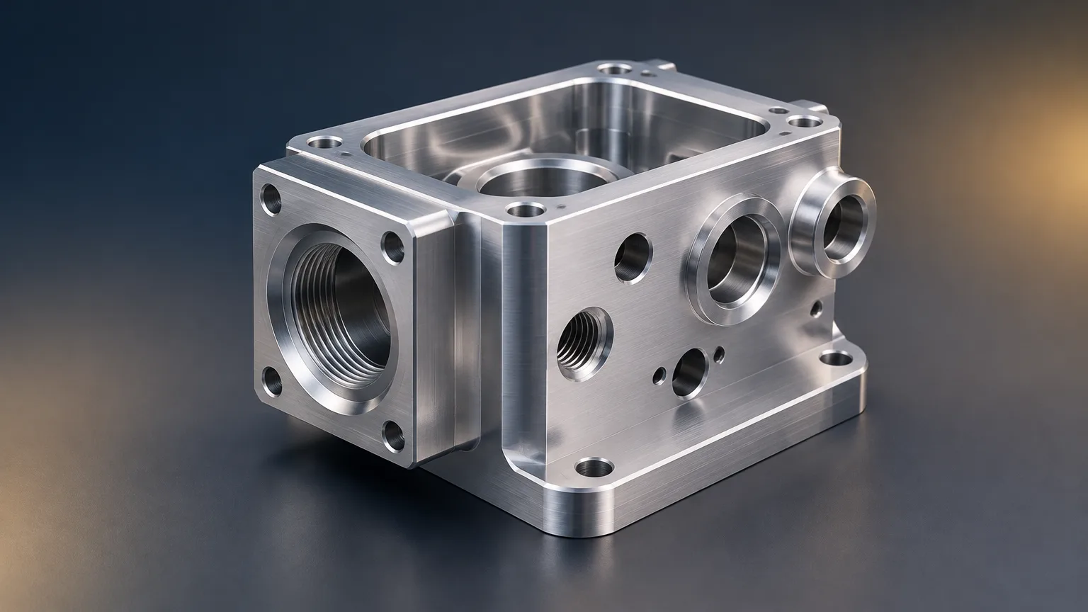
- Send STEP and a drawingMaterial, tolerances, datums and finish on the print.
- Machinability reviewSetup, tooling and tolerance feedback before cutting.
- Inspection before shippingDimensional checks against the controlled drawing.
Prototype machining is CNC machining of one-off or low-volume parts directly from CAD, so engineers can validate fit, form and function before production tooling. Prototype CNC machining covers milling, turning, drilling and tapping in metals and engineering plastics, typically held to about ±0.005 in (±0.13 mm) unless the drawing specifies tighter features.
What prototype machining is and when to use it
Prototype machining is the CNC machining of one-off or low-volume parts straight from a CAD model and drawing, with no hard tooling. Material is removed by milling, turning, drilling or related processes under computer control, so the same program can be adjusted between iterations.
It is used by design engineers, product developers, procurement managers and founders who need physical parts to test. Typical triggers are a design review, a fit check against an existing assembly, a functional test rig, a customer sample, or a pre-production pilot run.
When prototype CNC machining is the right route
- You need real material properties, not a visual model: machined prototypes behave like the production part.
- Tolerances matter now, because the part must mate with bearings, seals, threads or a housing.
- The geometry is prismatic or rotational: pockets, contours, holes, shafts and threaded features.
- You expect several design iterations and want to change the model without paying for a new mold.
- You need a small pilot batch, often 1 to 100+ pieces, to support testing or early builds.
Prototype machining process steps
Prototype machining is the CNC cutting of one-off or low-volume parts directly from CAD models, used to test fit, form and function before production tooling is built.
The process runs from quote to inspected parts in a fixed sequence. Each step is a checkpoint where the design or scope can still change cheaply.
- 1. Send the CAD model and controlled drawing Provide native or neutral CAD plus a drawing stating material and grade, tolerances, datums, finish, threads, quantity and inspection needs. Cover unspecified tolerances with an ISO 2768 class.
- 2. DFM and machinability review The supplier reviews workholding access, tool reach, wall thickness, corner radii and tolerance stack-up. Deep cavities and thin walls raise cost and distortion risk, so geometry is simplified here.
- 3. Quote and process plan The quote covers material, machining time, programming and setup, finishing and inspection. Confirm the routing: milling for prismatic parts, turning for rotational parts, mill-turn for fewer setups.
- 4. Programming and setup CAM programming, stock preparation, fixturing and tool selection happen before the first cut. Prototype quantities spread this cost over very few parts.
- 5. Machining Parts are cut on CNC mills, lathes or mill-turn machines, with drilling and tapping for standard holes and threads. Wire EDM covers narrow slots or hard-material features.
- 6. Finishing Deburring, bead blasting, anodizing, plating or painting are applied as specified. Define finishing on the drawing because it affects dimensions and lead time.
- 7. Inspection and delivery Dimensions are checked against the drawing, with first-article or dimensional reports where required. Parts ship to the address on the purchase order.
Materials and finishes for CNC prototypes
Material choice drives machinability, strength and cost more than any other single decision. The grades below are common starting points; verify properties against the applicable ASTM, EN or producer datasheet.
| Material | Grade | Properties | Typical uses |
|---|---|---|---|
| Aluminum | 6061-T6 | Lightweight, corrosion-resistant, generally machinable. | Brackets, housings, prototypes, fixtures, aerospace parts. |
| Stainless steel | 304 | Corrosion resistance, toughness, broad availability; work-hardening can increase machining difficulty. | Food, chemical, medical, general industrial components. |
| Stainless steel | 316 | Improved corrosion resistance relative to 304, especially in chloride environments. | Marine, chemical-processing, medical, sanitary hardware. |
| Carbon steel | AISI 4140 | Strength and toughness; machinability varies with heat treatment. | Shafts, tooling, fixtures, mechanically loaded parts. |
| Engineering plastic | POM/Delrin | Low friction, dimensional stability, good machinability. | Bushings, wear parts, guides, electromechanical components. |
Finishes and secondary operations
- As-machined with deburring and edge break: the default for fit and function checks.
- Bead blasting for a uniform matte surface on aluminum and stainless steel.
- Anodizing (Type II or Type III) for aluminum; show masking on the drawing.
- Passivation for stainless steel to remove free iron from machined surfaces.
- Zinc or nickel plating for carbon steel exposed to handling or moisture.
- Painting or powder coating where appearance matters; specify color and gloss.
Prototype machining specs and tolerances
Tolerance is a cost lever, so specify it per feature rather than globally. The ranges below are supplier capability references, not universal standards; confirm them for the feature, material and inspection method.
| Parameter | Typical range | Standard or source |
|---|---|---|
| General CNC dimensional tolerance | ±0.005 in (±0.13 mm) | Reported common/default range; verify with the supplier and drawing. |
| CNC milling, general features | ±0.002–0.004 in (±0.05–0.10 mm) | Supplier capability reference; not a universal standard. |
| CNC milling, tight features | ±0.0004–0.0010 in (±0.01–0.025 mm) | Supplier capability reference; depends on geometry, material and inspection. |
| CNC turning, general | ±0.001–0.002 in (±0.025–0.05 mm) | Supplier capability reference. |
| CNC turning, precision | ±0.0002–0.0004 in (±0.005–0.01 mm) | Supplier capability reference; must be confirmed for the feature. |
| General unspecified tolerances | ISO 2768-f, -m, -c or -v classes | ISO 2768 designation; class and applicable part must appear on the drawing. |
| Geometric tolerancing | Feature-specific; no single universal range | ASME Y14.5 or ISO 1101, as specified by the drawing. |
Design tips that lower prototype machining cost
Most prototype cost sits in programming, setup and inspection, not cutting time. These design choices reduce all three.
- Tolerance only what functions. Relax noncritical dimensions to the general tolerance and reserve tight limits for mating features.
- Design for standard tooling. Match cutter radii to common end mills and avoid deep, narrow pockets that force long, fragile tools.
- Keep walls and floors thick enough to resist deflection; thin walls raise distortion and scrap risk.
- Use standard thread sizes; nonstandard pitches need special taps and extra setup.
- Minimize setups and part orientations; each extra face adds fixturing and re-datuming error.
- Avoid unnecessary fine-finish callouts; they add passes and inspection time without improving function.
- Consolidate compatible features into one part where the assembly allows.
Typical prototype machining applications
Prototype CNC machining fits parts that must be tested in real material and to real dimensions. The examples below are typical, not exhaustive.
- Automotive: brackets, sensor housings, mounting plates, linkage components, jigs and fixtures for test rigs.
- Industrial equipment: manifolds, valve bodies, pump components, drive shafts and bushings.
- Medical and laboratory: instrument housings, fixtures, guides and fluid-handling components in stainless steel or engineering plastic.
- Aerospace and defense: lightweight aluminum brackets, structural fittings and ground-support tooling.
- Electronics and robotics: enclosures, heat-sink interfaces, end-effector plates and gearbox adapters.
- Consumer products: functional models, mechanism prototypes and pre-production samples for review.
Routing by geometry
CNC milling
- Prismatic parts, pockets, contours, holes and multi-axis features.
- Requires workholding access; deep cavities and thin walls increase cost and distortion risk.
CNC turning and mill-turn
- Turning suits rotational parts such as shafts, bushings and threaded components.
- Mill-turn combines turning and milling with fewer setups and improved feature alignment.
What drives prototype machining cost
Prototype machining is priced from the drawing, not from a catalog. Five variables explain most of the difference between quotes.
- Quantity and setup amortization. Low quantities carry programming and setup cost spread over very few parts.
- Tolerance and inspection. Tighter features mean slower feeds, additional finishing passes and more measurement.
- Geometry and workholding. Deep cavities, thin walls, long slender features and awkward orientations add fixtures and risk.
- Material. Machinability, work-hardening behavior and stock availability change cycle time and price.
- Finishing and documentation. Anodizing, plating, painting, first-article reports and dimensional reports are separate line items.
Why order prototype machining through Sourcing Repository
Sourcing Repository is a manufacturing broker. It does not own factories or machines; it collects quotes from a vetted supplier network, manages quality and inspection, and delivers the parts.
- One contact for the whole order, instead of chasing several machine shops for quotes and status.
- Quotes collected from a vetted supplier network and matched to your material, tolerance and quantity.
- Quality and inspection managed on your behalf, against the controlled drawing you supply.
- Deposit and payment terms are confirmed in writing before the order is released.
- Quote turnaround is 5–7 working days from receipt of a complete CAD file and drawing.
Have a drawing to quote?
Upload it with quantity and material to start a quote.
FAQ
Common questions
How can buyers reduce custom CNC machining cost?
Relax noncritical tolerances, simplify setups, use standard tools and threads, avoid deep cavities, select machinable materials and consolidate compatible features into one part. Most savings come from reducing programming, setup and inspection time rather than cutting speed.
What files should a CNC machining company receive?
Provide a native or neutral CAD file plus a controlled drawing specifying material and grade, tolerances, datums, surface finish, threads, quantity and inspection requirements. Unspecified tolerances should be covered by an ISO 2768 class stated on the drawing.
What is a realistic general CNC tolerance?
A commonly reported default is ±0.005 in (±0.13 mm), but actual capability depends on process, material, geometry and supplier equipment. Milling general features are often quoted at ±0.002–0.004 in (±0.05–0.10 mm), and turning general at ±0.001–0.002 in (±0.025–0.05 mm).
How does precision CNC machining cost change with tolerance?
Tighter tolerances can require slower cutting, extra passes, controlled environments and more inspection. One supplier reports non-linear cost increases below ±0.005 in, so specify tight limits only on features that actually need them.
Related resources
Keep reading
Ready when you are
Get a prototype machining quote
Send your CAD file, controlled drawing and quantity. Sourcing Repository collects quotes from a vetted supplier network, manages inspection and delivers inspected CNC prototypes.
Your files stay confidential. NDA available on request.