
Process explained
Cut, form, join and finish flat sheet into drawing-compliant parts.
Definition and scope
Manufacturing guide
Sheet metal fabrication turns flat metal sheet into finished parts through cutting, forming, joining and finishing. This guide covers each step, common materials, tolerances and cost drivers.
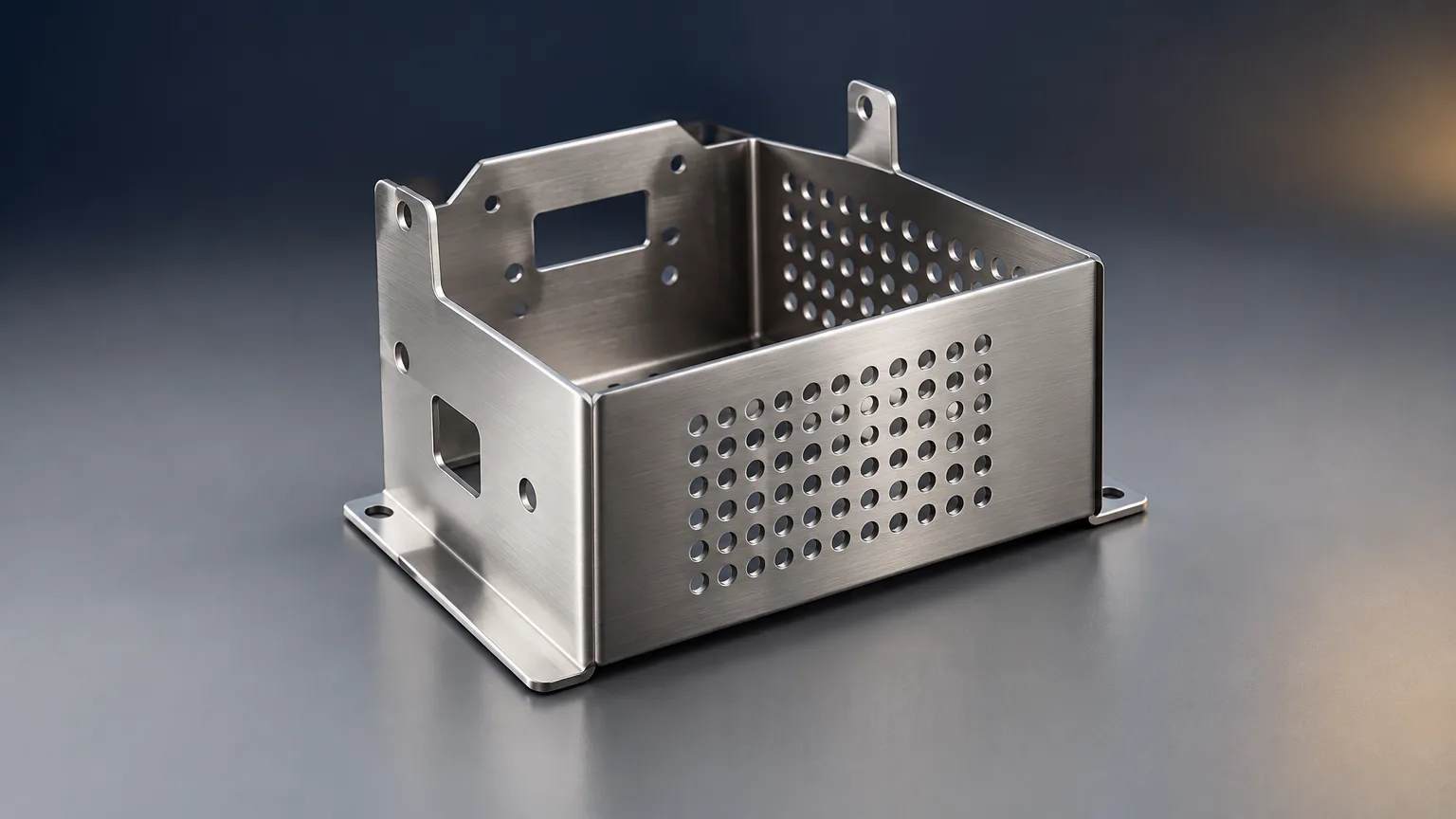
Cut, form, join and finish flat sheet into drawing-compliant parts.
From engineering review and material verification to inspection and packing.
Laser, punching, shearing, press brake, stamping, roll forming, welding, fastening.
Carbon, galvanized, stainless and aluminum sheet with specifications.
Material utilization and speed versus tolerance, tooling and distortion limits.
Thickness, tolerance class, bend sequence, welding code and inspection scope.
Automotive, industrial, HVAC, electronics, food and transportation parts.
Cost drivers and how to request a quote for fabricated parts.
The sheet metal fabrication process is a sequence of cutting, forming, joining and finishing steps that converts flat metal sheet into finished parts. It commonly includes laser or punched cutting, press-brake bending, stamping, welding, fastening, deburring and surface treatment. Sourcing Repository collects quotes from vetted suppliers, manages quality and inspection, and delivers parts.
Sheet metal fabrication is the conversion of flat metal sheet into finished parts through cutting, forming, joining and finishing. The work starts from a flat blank and ends as a part that meets a drawing: correct material, thickness, geometry, tolerances and finish.
What is sheet metal work in practice? It is a chain of operations, not a single machine. A part may be laser cut, press-brake formed, welded, deburred and coated before it is inspected and packed. Each operation adds capability and adds tolerance stack-up, so the drawing must state what matters.
Sheet metal processing is usually chosen over machining when the part is thin-walled, made from flat stock, and produced in quantities where material utilization and forming speed matter. Machining removes material from solid blocks and suits complex 3D geometry and tight precision features. The two are often combined: a fabricated enclosure with machined inserts, for example.
The sheet metal fabrication process runs from engineering review to packed parts, in a sequence adjusted to the part and volume. Some parts skip joining or finishing entirely.
Lead-time variation in the sheet metal fabrication process comes from material availability, tooling, capacity, outside processing, inspection and rework. A complete RFQ removes most avoidable delay.
Sheet metal processing splits into cutting, forming, joining and finishing families, each with different economics. Within the sheet metal fabrication process, the table below shows where each option fits.
| Process | Best fit | Main limitation |
|---|---|---|
| Laser cutting | Prototypes, low-to-medium volumes, intricate profiles, frequent design changes | Slower or less economical than stamping at very high volumes |
| Turret punching | Repeated holes and standardized features | May leave tool marks; geometry limitations |
| Shearing | Straight cuts and simple profiles | Limited to simple profiles; possible edge distortion |
| Press-brake forming | Low-to-medium volumes with varied bends | Springback and bend sequencing require control |
| Stamping | Large volumes of a stable design | Tooling cost and lead time are substantial |
| Roll forming | Long, constant profiles | Unsuitable for isolated or highly variable shapes |
| Welding and brazing | Structural joints in assemblies | Heat can cause distortion; qualified procedures required |
| Mechanical fastening | Serviceable or heat-sensitive assemblies | Adds hardware, labor and possible corrosion interfaces |
| Comparison | Key differences |
|---|---|
| Sheet-metal fabrication vs machining | Fabrication forms and joins sheet with high material utilization; machining removes material and is better for solid blocks, precision features and complex 3D geometry. |
| Laser cutting vs turret punching | Laser cutting offers flexible profiles and no dedicated punch tooling; punching is often faster for repeated holes and standardized features. |
| Press-brake forming vs stamping | Press brakes suit variable, lower-volume work; stamping requires dedicated tooling but supports high production rates. |
| Welding vs mechanical fastening | Welding creates permanent joints but introduces heat; fastening avoids heat distortion and supports disassembly but requires hardware and access. |
Material choice sets formability, weldability, corrosion behavior and cost. Four sheet families cover most fabricated parts, and each must be specified by standard and grade, not by a trade name alone.
| Material | Specification | Properties | Typical uses |
|---|---|---|---|
| Low-carbon steel sheet | ASTM A1008/A1008M; grade varies by product | Good formability, weldability and low cost; corrosion protection may require coating | Cabinets, brackets, chassis, ductwork and general fabricated parts |
| Galvanized steel sheet | ASTM A653/A653M | Zinc coating improves atmospheric corrosion resistance; welding can affect coating locally | HVAC, enclosures, roofing, cold-formed framing and outdoor components |
| Stainless steel sheet | ASTM A240/A240M; grades must be specified | Corrosion resistance and cleanability; higher cost and forming springback than carbon steel | Food equipment, medical equipment, chemical equipment and architectural parts |
| Aluminum sheet | Alloy and temper must be specified; unverified source grade | Low density, corrosion resistance and good machinability; relatively low stiffness and possible galling | Transportation, housings, electronics and lightweight structures |
Thickness is unverified without material, gauge and product standard. Specify nominal thickness, permitted tolerance and the applicable ASTM or EN material standard. Gauge alone can be ambiguous between materials and suppliers, so state thickness in inches with the metric equivalent.
The sheet metal fabrication process is efficient for thin-walled parts and high material utilization, but it has real constraints on geometry, tolerance and tooling. Weigh both sides before committing a design.
| Parameter | Typical range | Standard or source |
|---|---|---|
| Maximum thickness for AWS D9.1/D9.1M scope | Up to 0.239 in [6.07 mm] | AWS D9.1/D9.1M, Sheet Metal Welding Code |
| AWS D1.3/D1.3M sheet-steel scope | Up to 0.197 in [5 mm]; yield point no greater than 80 ksi [550 MPa] | AWS D1.3/D1.3M:2025 |
| General linear and angular tolerances | Class-dependent; specify ISO tolerance class on drawing | ISO/DIS 2768 applies to formed sheet-metal workpieces |
| Thickness | Unverified without material, gauge and product standard | Specify nominal thickness, permitted tolerance and applicable ASTM or EN material standard |
| Bend angle and flange dimensions | Unverified; depends on tooling, alloy, thickness, bend radius and process | Use drawing-specific tolerances; general ISO tolerances may apply only where invoked |
| Flatness and squareness | Unverified; depends on material, size, forming and inspection method | Define acceptance criteria on the drawing or purchase specification |
A manufacturable sheet metal process starts with design rules set before the first cut, because most fabrication problems are designed in. These rules keep a part formable and inspectable throughout the sheet metal fabrication process, without rework loops.
Sheet metal fabrication serves any product built from thin-walled, flat-stock parts, which is why it dominates enclosures, brackets and structural panels. Automotive and industrial equipment are the largest users.
The same part family can be produced by different routes. A bracket may be laser cut and press-brake formed at low volume, then stamped once demand stabilizes. Choosing the route early avoids tooling spend on a design that is still moving.
Cost in the sheet metal fabrication process is driven by material, processing and quality requirements, not by a single hourly rate. Understanding the drivers lets you quote the same design to several suppliers and compare like with like.
A complete RFQ shortens quoting and reduces surprises. Provide 2D drawings, 3D CAD, material grade, thickness, quantity, finish, tolerances, inspection requirements, packaging and delivery location. Sourcing Repository collects quotes from a vetted supplier network, manages quality and inspection, and delivers parts; typical quote turnaround is 5-7 working days.
Upload it with quantity and material to start a quote.
FAQ
Lead time varies with material availability, engineering review, tooling, capacity, outside processing, inspection, rework and shipping constraints. Tooling-heavy work such as stamping is especially exposed. A complete RFQ with drawings, material, tolerances and inspection scope removes most avoidable delay.
Provide 2D drawings, 3D CAD, material grade, thickness, quantity, finish, tolerances, inspection requirements, packaging and delivery location. State the applicable material standard and any welding code so the supplier quotes the same scope.
Specify nominal thickness and permitted tolerance, plus the applicable ASTM or EN material standard. Gauge alone can be ambiguous between materials and suppliers, and thickness is unverified without material, gauge and product standard.
Yes, with appropriate procedures, ventilation, preparation and coating-repair requirements, and the applicable welding code must be identified. Welding can affect the zinc coating locally, so plan for repair and inspect the joint area.
Related resources
Ready when you are
Send your drawings, material, thickness and inspection requirements. Sourcing Repository collects quotes from a vetted supplier network, manages quality and inspection, and delivers parts.
Your files stay confidential. NDA available on request.