
Automotive Prototype Parts
Prototype Engineering for Automotive Prototype Parts
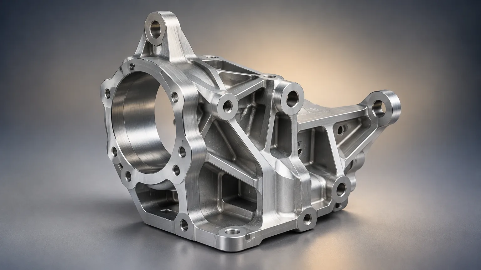
Prototype engineering turns your CAD and requirements into testable automotive prototype parts. SR collects quotes from a vetted supplier network, manages quality and inspection, and delivers parts to your dock.
- CNC machining
- 3D printing
- Sheet metal
- Vacuum casting
- Send CAD and drawingsNative CAD, neutral CAD, PDF drawings, revision level.
- DFM review before cuttingTolerance, interface and manufacturability checks.
- Inspection before shipmentDimensional checks against your tolerance scheme.
Prototype engineering is the design, fabrication and evaluation of representative parts or assemblies before production. For automotive prototype parts, SR collects quotes from a vetted supplier network, routes the work to the right process, manages DFM review and inspection, and delivers parts. Typical lead time is 5-7 working days for quoting.
What prototype engineering for automotive prototype parts is
Prototype engineering is the design, fabrication and evaluation of representative parts, assemblies or electronic products before production. It converts requirements into testable hardware and identifies design, manufacturing, performance and compliance risks early, when changes are still cheap.
This service is for engineers, procurement managers and founders who need automotive prototype parts that behave like the intended production part. It fits three situations: a new design that has never been built, a design change that needs validation, and a supplier or process change that needs a physical check before tooling.
When to use prototype engineering
- You need fit, form or function evidence before committing to production tooling.
- You need engineering validation builds for a bracket, housing, duct, fixture or PCB assembly.
- You need to verify tolerances and interfaces between mating parts.
- You need a small batch of production-like parts for bench, rig or vehicle testing.
- You need to compare two design options with real hardware instead of simulation alone.
Prototype engineering process steps
The process runs from requirements to inspected parts in a fixed sequence, so each step has a defined output. SR manages the steps and keeps one point of contact across the supplier network.
- 1. Requirements and file intake You send native CAD, neutral CAD, drawing PDFs, revision level, material, finish, quantity, tolerance scheme, inspection needs and test requirements. Missing data is flagged before quoting.
- 2. Process selection The build is matched to a route: CNC machining, FDM/SLA/SLS printing, sheet-metal fabrication, vacuum casting, metal additive manufacturing or electronics contract manufacturing. Selection follows the test objective, not preference.
- 3. DFM review Suppliers review geometry, tolerances, interfaces, datum scheme, wall thickness, tool access and material behavior. Findings come back as a short list of changes with cost and schedule impact.
- 4. Quote and release Quotes from the vetted network are consolidated into one comparison. After you approve, the build is released to the selected supplier with the agreed drawing revision.
- 5. Fabrication Parts are machined, printed, formed, cast or assembled. In-process checks catch setup drift before a full batch is run.
- 6. Inspection and documentation Dimensional inspection is performed against the tolerance scheme. Results, material certificates where applicable and non-conformance notes are compiled.
- 7. Delivery and feedback Parts ship to your dock. Test feedback feeds the next revision, and the same files can be re-released for a second build or for production quoting.
Materials and finishes for automotive prototype parts
Material choice follows the test objective. A functional prototype needs production-equivalent behavior; an appearance model needs form and finish. Grades below are typical starting points, and exact grade, condition and properties require supplier certificates and applicable material standards.
| Material | Grade | Properties | Typical uses |
|---|---|---|---|
| Aluminum | 6061-T6 | Lightweight, machinable, corrosion resistant, moderate strength. | Automotive brackets, housings, fixtures, functional prototypes. |
| Stainless steel | 304 | Corrosion resistant, weldable, moderate strength. | Enclosures, brackets, fluid-contact hardware. |
| Engineering plastic | Grade-specific | Properties depend on polymer, reinforcement, process and orientation. | Housings, clips, ducts, insulators, ergonomic models. |
| Polycarbonate | Grade-specific | Impact resistant and electrically insulating; grade-specific performance applies. | Covers, transparent prototypes, guards, electronic housings. |
| PCB laminate | FR-4 | Glass-reinforced epoxy laminate with grade-specific electrical and thermal performance. | Rigid prototype printed circuit boards. |
Finishes and post-processing
- As-machined or as-printed finish for fit checks and internal parts.
- Bead blast, brushed or anodized finish for aluminum appearance parts.
- Paint, texture or vapor smoothing for visible covers and guards.
- Support removal, stress relief and surface finishing for metal additive parts.
- Conformal coating and soldering per J-STD-001 for prototype electronics.
Prototype engineering specs and tolerances
Prototype engineering specs and tolerances depend on the process: typical CNC prototype tolerance is ±0.0004–0.002 in (±0.01–0.05 mm), while printing and casting run wider. These are supplier guidance, not capability guarantees. Specify the functional requirement rather than a blanket tight tolerance.
Prototype engineering is the design, fabrication and evaluation of representative parts, assemblies or electronic products before production. It turns requirements into testable hardware and exposes design, manufacturing, performance and compliance risks early.
| Parameter | Typical range | Source |
|---|---|---|
| CNC general prototype tolerance | ±0.0004–0.002 in (±0.01–0.05 mm) | Rapid Protos automotive prototyping guide |
| FDM, SLA or SLS tolerance | ±0.004–0.012 in (±0.1–0.3 mm) | Rapid Protos automotive prototyping guide |
| FDM dimensional variation | ±0.012–0.020 in (±0.3–0.5 mm) | Simple Machining rapid prototyping guide |
| Metal additive tolerance | ±0.002–0.004 in (±0.05–0.1 mm) | Rapid Protos automotive prototyping guide |
| Vacuum-casting tolerance | ±0.008–0.012 in (±0.2–0.3 mm) | Rapid Protos automotive prototyping guide |
| SLA layer thickness | 0.002–0.006 in (0.05–0.15 mm) | Protolabs rapid-prototyping guide |
| CNC controlled datum features | About ±0.002 in (±0.05 mm) | JLC CNC functional prototyping guide |
Design tips that lower prototype engineering cost
Most prototype cost is set in the CAD model, before any quote is issued. These design-for-manufacturing moves reduce setups, material waste and inspection time without weakening the test.
- Tolerance only what functions. A blanket tight tolerance forces extra setups and inspection on features that do not matter.
- Design for one setup where possible. Features reachable from a single orientation cut machining time and setup error.
- Use standard stock sizes and available materials. Custom stock adds lead time and waste.
- Keep wall thickness uniform and avoid thick-to-thin transitions that warp or sink.
- Add generous fillets and avoid sharp internal corners that need small tools or slow passes.
- Consolidate parts where additive manufacturing allows it, reducing assembly and fasteners.
- Avoid premature tooling. Prove the design with a prototype route before committing to production tooling.
- State the datum scheme and inspection plan on the drawing so inspection is unambiguous.
Typical automotive prototype parts and applications
Automotive prototype parts span metal, plastic and electronic content. The examples below are typical of engineering validation builds and low-volume test programs.
| Process route | Example parts | Typical industry use |
|---|---|---|
| CNC machining | Brackets, housings, fixtures, sensor mounts, manifolds | Automotive, motorsport, industrial equipment |
| FDM, SLA or SLS printing | Ducts, clips, covers, ergonomic models, jigs | Automotive, consumer products, tooling |
| Sheet-metal fabrication | Enclosures, panels, structural brackets, heat shields | Automotive, energy, industrial enclosures |
| Vacuum casting | Small plastic batches with production-like appearance, elastomer seals | Automotive interiors, consumer products |
| Metal additive manufacturing | Complex internal channels, consolidated parts, lightweight nodes | Motorsport, aerospace, thermal management |
| Electronics contract manufacturing | Prototype PCB assemblies, control modules, harness boards | Automotive electronics, instrumentation |
Appearance versus functional prototypes
Appearance models prioritize form and finish. Functional prototypes prioritize material behavior, interfaces and test performance. State which one the build is for, because the process, material and inspection plan differ.
What drives prototype engineering cost
Prototype cost is driven by geometry, process, material and inspection scope, not by a single rate. The same part can differ several times over depending on how these factors are set.
- Geometry complexity: undercuts, deep pockets, thin walls and sharp internal corners add setups and tool time.
- Process route: CNC generally provides stronger production-like parts and tighter tolerances; printing usually offers faster iteration and more geometric freedom.
- Material: production-grade metals and plastics cost more than commodity print resins, and metal additive powder is a significant share of cost.
- Size, mass and material utilization: larger parts consume more stock and machine time.
- Tolerance and inspection: tight tolerances and full dimensional reports add measurement time.
- Quantity: unit cost falls with quantity, but setup cost is spread across the batch.
- Post-processing: heat treatment, anodizing, painting, support removal and surface finishing.
- Tooling and patterns: vacuum casting requires a master pattern, and prototype tooling has limited mold life.
- Electronics scope: sourcing, NPI, testing and rework support add cost beyond bare board fabrication.
Why order automotive prototype parts through SR
Ordering automotive prototype parts through SR gives you one contact for quotes, quality and delivery. SR is a manufacturing broker and does not own factories or machines. It collects quotes from a vetted supplier network, manages quality and inspection, and delivers parts.
What SR does
- Consolidates supplier quotes into one comparison.
- Routes each build to the process that matches the test objective.
- Manages DFM review, drawing revisions and supplier communication.
- Manages quality and inspection against your tolerance scheme.
What SR does not do
- Own factories, machines or tooling.
- Replace your design authority or test program.
- Guarantee published process tolerances, which depend on supplier equipment and geometry.
Have a drawing to quote?
Upload it with quantity and material to start a quote.
FAQ
Common questions
Which process is best for automotive prototype parts?
Select by test objective: CNC for durable tight-tolerance parts, sheet metal for structural assemblies, and additive manufacturing for rapid geometry iteration. Vacuum casting suits small plastic batches with production-like appearance, and electronics contract manufacturing covers prototype PCB assemblies.
Can prototype parts use production materials?
Yes. CNC, sheet metal, and selected additive or casting routes can use production-equivalent materials. Verify grade, process condition and properties, because printed and cast parts may not match wrought or molded behavior. Request material certificates where the test depends on them.
How can prototype cost be reduced?
Simplify geometry, reduce setups, use available materials, limit unnecessary tight tolerances, consolidate inspection requirements, and avoid premature tooling. Consolidating parts where additive manufacturing allows it also cuts assembly and fastener cost.
What files should a buyer provide?
Provide native CAD, neutral CAD, drawing PDFs, revision level, material, finish, quantity, tolerance scheme, inspection needs and test requirements. State the datum scheme and any standards such as ASME Y14.5 or ISO 2768 so quoting and inspection are unambiguous.
Related resources
Keep reading
Ready when you are
Get automotive prototype parts quoted
Send your CAD, drawings and test requirements. SR collects quotes from a vetted supplier network, manages DFM review and inspection, and delivers parts to your dock.
Your files stay confidential. NDA available on request.