
Tolerances explained
What CNC machining tolerances are and why the drawing must state them.
CNC Machining Guide
CNC machining tolerances define how much a finished feature may deviate from the drawing. This guide covers typical ranges, ISO 2768 defaults, surface finish, and how tolerance choices drive cost.
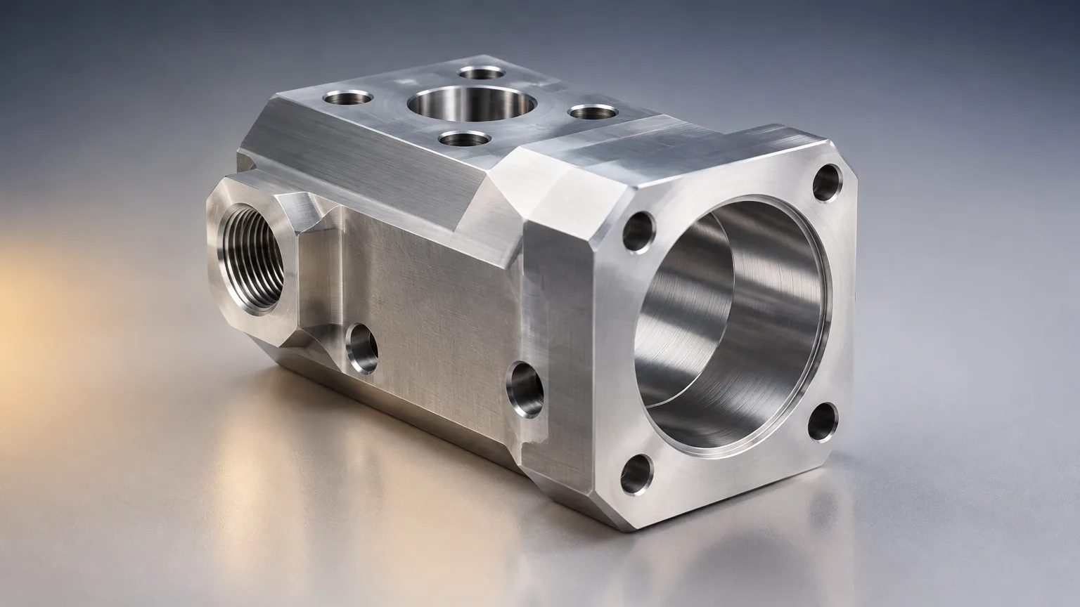
What CNC machining tolerances are and why the drawing must state them.
From drawing review to inspection, step by step.
Dimensional and geometric tolerances with typical ranges.
Aluminum, stainless, carbon steel, and engineering plastics.
What tight tolerances buy and what they cost.
Practical rules for specifying tolerances on a drawing.
Automotive, medical, aerospace, and industrial uses.
Cost drivers and how to start a quote.
CNC machining tolerances are the allowable dimensional deviations on a machined feature, stated on the drawing in inches or millimetres. A commonly reported general default is ±0.005 in (±0.13 mm), while milling and turning can hold tighter feature-specific ranges. Tolerance, material, geometry and inspection requirements all affect achievable accuracy and cost.
CNC machining tolerances are the permitted limits of dimensional variation for a feature produced by computer-controlled material removal. They are set on the drawing as a nominal size plus an allowed band, not assumed by the supplier.
Precision CNC machining is computer-controlled removal of material from a workpiece using milling, turning, drilling, or related processes. Accuracy comes from programming, fixturing, tooling, temperature management, and inspection.
Two numbers matter on every drawing: the nominal size and the tolerance band around it. In a typical example, a shaft called out at 1.000 in (25.40 mm) ±0.005 in (±0.13 mm) may measure anywhere from 0.995 to 1.005 in (25.27 to 25.53 mm) and still conform. Anything outside that band is nonconforming, however good the surface looks.
Tolerance is not the same as surface finish. Tolerance controls size and location; surface finish controls the texture left by the cutting tool. Specify each separately.
Tolerance control is a chain of decisions from drawing review to final inspection. Each step either protects or erodes the accuracy the drawing demands.
Tolerance types fall into two families: dimensional tolerances that control size and location, and geometric tolerances that control form, orientation, and position. Dimensional tolerances are usually plus/minus values or limit dimensions. Geometric tolerancing has no single universal range; it follows ASME Y14.5 or ISO 1101 as the drawing specifies.
| Parameter | Typical range | Standard or source |
|---|---|---|
| General CNC dimensional tolerance | ±0.005 in (±0.13 mm) | Reported common/default range; verify with the supplier and drawing. |
| CNC milling, general features | ±0.002–0.004 in (±0.05–0.10 mm) | Supplier capability reference; not a universal standard. |
| CNC milling, tight features | ±0.0004–0.0010 in (±0.01–0.025 mm) | Supplier capability reference; depends on geometry, material, and inspection. |
| CNC turning, general | ±0.001–0.002 in (±0.025–0.05 mm) | Supplier capability reference. |
| CNC turning, precision | ±0.0002–0.0004 in (±0.005–0.01 mm) | Supplier capability reference; must be confirmed for the feature. |
| General unspecified tolerances | ISO 2768-f, -m, -c, or -v classes | ISO 2768 designation; class and applicable part must appear on the drawing. |
| Geometric tolerancing | Feature-specific; no single universal range | ASME Y14.5 or ISO 1101, as specified by the drawing. |
| Route | Strengths | Limitations |
|---|---|---|
| CNC milling | Prismatic parts, pockets, contours, holes, multi-axis features | Requires workholding access; deep cavities and thin walls increase cost and distortion risk |
| CNC turning | Rotational parts such as shafts, bushings, threaded components | Less suitable for non-rotational geometry; long slender parts may deflect |
| Mill-turn machining | Combines turning and milling with fewer setups and improved feature alignment | Machine and programming costs are generally higher |
| CNC drilling and tapping | Fast production of standardized holes and threads | Hole location, chip evacuation, and deep-hole access can limit capability |
| Wire EDM | Narrow slots and hard-material features with reported capability of about ±0.0002–0.0004 in (±0.005–0.010 mm) | Requires electrically conductive material; generally slower than milling |
Material behavior sets the practical accuracy floor. Stiffness, thermal expansion, work-hardening, and chip formation all change how a cut behaves, so the same tolerance can be routine in one material and difficult in another.
| Material | Grade | Properties | Typical uses |
|---|---|---|---|
| Aluminum | 6061-T6 | Lightweight, corrosion-resistant, and generally machinable | Brackets, housings, prototypes, fixtures, aerospace parts |
| Stainless steel | 304 | Corrosion resistance, toughness, broad availability; work-hardening can increase machining difficulty | Food, chemical, medical, general industrial components |
| Stainless steel | 316 | Improved corrosion resistance relative to 304, especially in chloride environments | Marine, chemical-processing, medical, sanitary hardware |
| Carbon steel | AISI 4140 | Strength and toughness; machinability varies with heat treatment | Shafts, tooling, fixtures, mechanically loaded parts |
| Engineering plastic | POM/Delrin | Low friction, dimensional stability, good machinability | Bushings, wear parts, guides, electrical-mechanical components |
Metal and plastic differ in stiffness, thermal expansion, cutting behavior, workholding, tool selection, and dimensional response. Plastics move more with temperature and can deflect under clamping force, while stainless steels such as 304 work-harden and demand different cutting strategies. Supplier-specific limits must be verified for the material and grade you specify.
Tight tolerances buy function and reliability, but they are not free. The trade-off is between what the assembly needs and what the process can hold economically.
Standard CNC versus precision CNC is largely a difference in feature requirements, setup control, inspection depth, and cutting strategy rather than a different machine category. Reserve the tightest bands for features that truly need them.
Good drawings make tolerance decisions explicit. The following rules reduce ambiguity and cost without weakening the part.
Tolerance requirements follow the application. Automotive and industrial assemblies often hinge on a small number of critical interfaces, while the rest of the part can run to general tolerances.
Prototype CNC and production CNC differ in emphasis: prototype work prioritizes speed and flexibility, while production work emphasizes repeatability, process control, fixtures, and optimized cycle time. Tolerance strategy should shift accordingly.
Cost is driven by how hard the drawing is to satisfy repeatedly. The main drivers are tolerance tightness, material machinability, feature geometry, number of setups, inspection depth, and finishing requirements.
To reduce cost, relax noncritical tolerances, simplify setups, use standard tools and threads, avoid deep cavities, select machinable materials, and consolidate compatible features. When comparing suppliers, compare verified process capability, material traceability, inspection equipment, certifications, capacity, lead time, corrective-action practice, and comparable sample work.
Sourcing Repository collects quotes from a vetted supplier network, manages quality and inspection, and delivers parts. Share your CAD file and controlled drawing to start; quote turnaround is typically 5–7 working days.
Upload it with quantity and material to start a quote.
FAQ
Send a native or neutral CAD file plus a controlled drawing. The drawing should specify material and grade, tolerances, datums, finish, threads, quantity, and inspection requirements, so the supplier quotes and inspects against the same information.
Buyers can lower cost by relaxing noncritical tolerances, simplifying setups, using standard tools and threads, and avoiding deep cavities. Choosing machinable materials and consolidating compatible features also helps, because each change reduces cutting time, setups, or inspection effort.
Tighter tolerances can require slower cutting, extra finishing passes, controlled environments, and more inspection. One supplier reports that cost rises non-linearly below about ±0.005 in (±0.13 mm), so tighten only the features that need it.
A commonly reported default is ±0.005 in (±0.13 mm), but actual capability depends on process, material, geometry, and supplier equipment. Confirm the range for each feature before release.
Related resources
Ready when you are
Send your CAD file and controlled drawing. Sourcing Repository collects quotes from a vetted supplier network, manages quality and inspection, and delivers parts. Quote turnaround is typically 5–7 working days.
Your files stay confidential. NDA available on request.