
Design for manufacturing DFM explained
Scope, goal, and how DFM relates to DFMA, prototyping and value engineering.
8 sections
DFM Engineering Guide
Design for manufacturing DFM is the practice of designing parts for consistent, economical production. This guide covers the review process, process trade-offs, tolerances, materials, cost drivers and design rules.
DFM: part manufacturability and production costvsDFMA: manufacturing plus assembly optimization
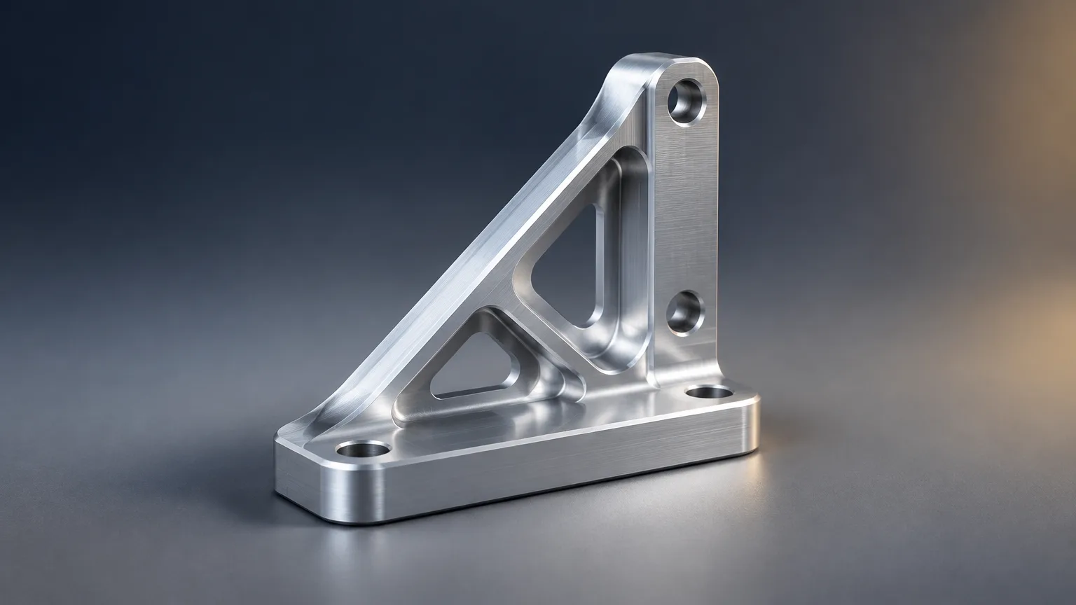
Scope, goal, and how DFM relates to DFMA, prototyping and value engineering.
Requirements baseline, process selection, geometry, tolerances, inspection, cost.
Machining, sheet metal, molding, additive, die casting and stamping trade-offs.
Aluminum, steel, stainless steel, engineering plastics and composites.
What DFM improves, and where the method stops short.
Tolerance strategy, tool access, inspection planning and cost reduction.
Design for manufacturing DFM is the practice of designing products and parts for consistent, economical production. It evaluates process selection, materials, geometry, tolerances, tooling, inspection, volume and downstream operations before release. Done early, DFM reduces tooling rework, scrap, bottlenecks and production cost.
Design for manufacturing DFM, also called design for manufacturability DFM, is a structured way to check that a part can be made repeatably at the target volume and cost before drawings are released. It is not a single checklist item; it is a decision sequence that runs across process choice, materials, geometry, tolerances, tooling, inspection and secondary operations.
The value shows up in the whole supply chain, not only at the machine. DFM work reduces tooling rework, scrap, bottlenecks and production cost, and it aligns design, manufacturing, procurement and quality teams on the same assumptions. A part that is easy to quote, fixture, measure and assemble is usually also easier to keep in production on schedule.
DFM emphasizes part manufacturability, while DFMA combines design for manufacturing with design for assembly. Prototyping validates concepts and may use different process limits than production. Value engineering compares function against total value rather than production feasibility alone.
Design for manufacturing DFM is the practice of designing parts for consistent, economical production by checking process, material, geometry, tolerances, tooling and inspection before release. A review tests the design against real process limits and closes with documented changes that the designer and supplier both accept.
Design for manufacturing DFM varies mainly by process, because each process has its own cost curve, tooling requirement and geometry limits. The table summarizes typical pros and cons; final selection depends on volume, geometry, tolerance and material.
| Process | Typical pros | Typical cons |
|---|---|---|
| CNC machining | High accuracy, broad material selection, suitable for prototypes and low-to-medium volumes. | Material waste, fixturing cost, and limited access to deep or internal features. |
| Sheet-metal fabrication | Efficient for enclosures, brackets, and formed parts; standard stock is widely available. | Bends, bend relief, springback, and tool access constrain geometry. |
| Injection molding | Low unit cost at high volume; repeatable molded plastic parts. | Tooling investment, draft requirements, shrinkage, warpage, and mold complexity. |
| Additive manufacturing | Fast design iteration and complex geometry without dedicated tooling. | Anisotropy, surface variation, build-size limits, and higher unit cost at volume. |
| Die casting | High-volume metal production with repeatable shapes and low machining content. | High tooling cost, draft requirements, porosity risk, and alloy/process constraints. |
| Stamping | Very low cycle time and unit cost for high-volume sheet parts. | Progressive tooling cost, forming limits, and poor economics at low volume. |
| Comparison | Key difference |
|---|---|
| DFM vs. DFMA | DFM emphasizes part manufacturability; DFMA combines design for manufacturing with design for assembly. |
| DFM vs. prototyping | DFM optimizes repeatable production; prototyping validates concepts and may use different process limits. |
| DFM vs. value engineering | DFM targets production feasibility and cost; value engineering evaluates function against total value. |
| General tolerance vs. GD&T | General tolerances provide defaults; GD&T explicitly controls functional geometry and relationships. |
| Machining vs. injection molding | Machining avoids mold tooling but has higher unit cost; molding requires tooling but suits high volume. |
Material selection during DFM balances function, process compatibility and availability. Grades shown here are unspecified because properties vary substantially by alloy, temper, resin or fiber system, so a recognized grade and condition should be stated whenever performance matters.
| Material | Typical properties | Typical uses |
|---|---|---|
| Aluminum | Lightweight, machinable, corrosion-resistant; exact properties depend on alloy and temper. | Machined housings, brackets, prototypes, and lightweight structures. |
| Steel | High strength and stiffness; machinability, corrosion resistance, and weldability depend on grade. | Structural parts, shafts, brackets, tooling, and welded fabrications. |
| Stainless steel | Corrosion resistance and strength vary substantially by grade and condition. | Fluid-contact parts, food equipment, medical components, and outdoor hardware. |
| Engineering plastic | Low density and corrosion resistance; creep, shrinkage, temperature capability, and strength vary by resin. | Molded housings, covers, bushings, clips, and insulating components. |
| Composite | Potentially high stiffness-to-weight ratio; properties depend on fiber, matrix, orientation, and process. | Lightweight panels, fixtures, aerospace parts, and specialized structures. |
Specify a recognized grade and condition when performance matters; unspecified grades are unverified for procurement. If a property is load-bearing or safety-related, confirm it against the applicable material standard rather than a generic family name.
DFM improves production feasibility and cost predictability, but it does not replace functional design work or process testing. The benefits are strongest when review happens early; the limits appear when teams treat DFM as a late drawing check.
Treat the output as a set of decisions with assumptions attached. When volume, material or tolerance changes later, revisit the review instead of carrying forward stale conclusions.
These practical rules reduce risk across most processes. Use them as prompts during design review, then confirm limits with the specific supplier and process before release.
DFM applies anywhere a design moves into repeatable production, and it matters most where volume, tooling or tolerances carry financial risk. Automotive programs, industrial equipment, consumer products and medical hardware all use the same core logic.
In each case the same question applies: can this design be produced, inspected and assembled repeatedly at the target volume with the selected process and material?
Cost in design for manufacturing DFM is driven by tooling, material, process time, tolerance, inspection and volume, not by a single line item. No process is universally cheapest. A design that is cheap at 500 units may be expensive at 50,000, and the reverse.
| Cost driver | What affects it | What reduces it |
|---|---|---|
| Tooling | Mold, die or progressive tool complexity and part count | Simpler geometry, fewer undercuts, higher volume amortization |
| Material | Grade, condition, stock availability and waste rate | Specified standard grades, nested layouts, near-net shapes |
| Process time | Setups, cycle time, fixturing and machine capability | Fewer setups, design for tool access, batch size aligned to volume |
| Tolerance | Tight or unnecessary tolerances and GD&T scope | General tolerances by default, functional tolerances only |
| Inspection | Critical characteristics, measurement method and documentation | Clear drawings, defined sampling, first-article discipline |
| Secondary operations | Finishing, deburring, marking, heat treatment, assembly | Explicit finish requirements and minimized handling steps |
Sourcing Repository does not own factories or machines. SR collects quotes from a vetted supplier network, manages quality and inspection, and delivers parts, with a typical quote turnaround of 5-7 working days. Send a drawing set, volume and material to start a manufacturability review and quote.
Upload it with quantity and material to start a quote.
FAQ
A DFM package should include CAD files, drawings, material and finish, critical tolerances, expected volume, inspection needs and assembly context. Marking functional versus reference dimensions helps the reviewer focus on decisions that affect cost and feasibility, rather than restating the drawing.
DFM review should occur during concept and design development, before tooling, supplier quotation or production release. Reviews held after tooling is cut can still fix small issues, but they rarely change cost structure or process selection, because the expensive commitments are already made.
No. Tighten only functional features, and use general tolerances elsewhere. Applying tight limits across all dimensions raises machining, molding or inspection cost without improving function. Reserve explicit tolerances or GD&T for relationships that affect fit, stack-up or performance.
There is no universal answer. Volume, geometry, material, tolerance, tooling and secondary operations determine cost. Machining avoids tooling but has higher unit cost; molding and stamping need tooling but win at high volume. Compare total cost at your actual annual quantity.
Related resources
Ready when you are
Send your CAD, drawings, material and volume. Sourcing Repository collects quotes from a vetted supplier network, manages quality and inspection, and delivers parts, with a typical quote turnaround of 5-7 working days.
Your files stay confidential. NDA available on request.