
DFM for casting
Draft, wall thickness, porosity risk and alloy choices for cast parts.
Sourcing Repository Guides
This DFM manufacturing guide explains how to design parts for consistent, economical production. It covers process selection, materials, tolerances, cost drivers and supplier review.
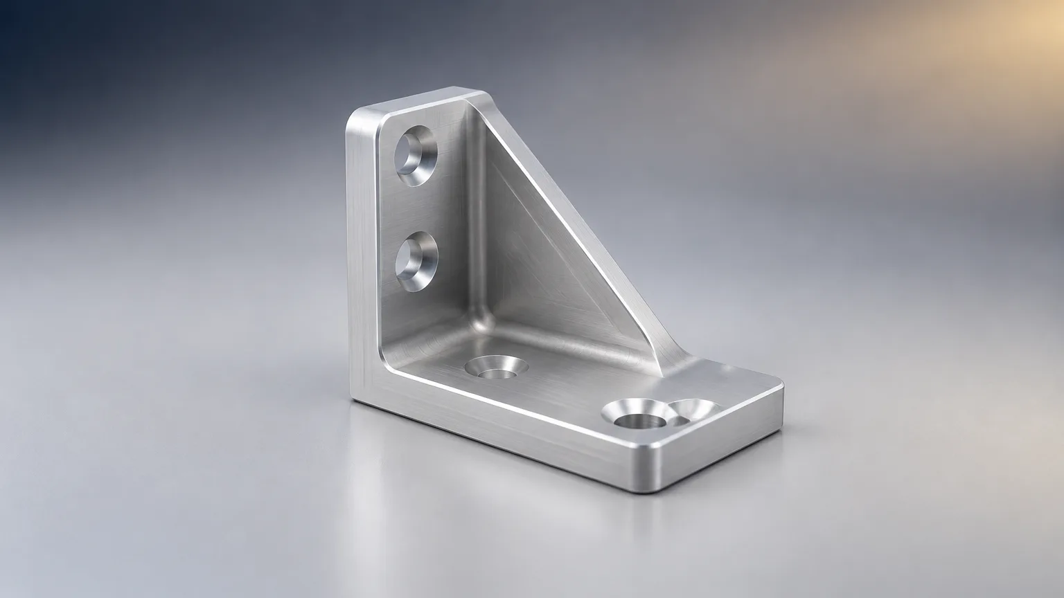
Draft, wall thickness, porosity risk and alloy choices for cast parts.
Feature access, fixturing, tool reach and machining tolerance limits.
Bend radii, bend relief, springback and tool access for formed parts.
Core rules that apply across processes and materials.
How DFM combines with design for assembly to cut part count and cost.
General tolerances, datum schemes and geometric controls.
Design for Manufacturing (DFM) is the practice of designing parts for consistent, economical production. A DFM manufacturing guide evaluates process selection, materials, geometry, tolerances, tooling, inspection, volume and downstream operations before release. The goal is to reduce tooling rework, scrap, bottlenecks and production cost while keeping function intact.
Design for Manufacturing (DFM), also called design for manufacturability, is the practice of designing products and parts for consistent, economical production. It evaluates process selection, materials, geometry, tolerances, tooling, inspection, volume and downstream operations before release. This DFM manufacturing guide walks through those decisions in the order most engineering teams face them.
The guide is written for engineers, procurement managers and founders sourcing custom parts, with automotive examples where useful. It does not replace a supplier's process review. It gives you the vocabulary, checklists and questions to run that review well.
Read the chapters in sequence for a full picture, or jump to the process or material section that matches your current decision. Each chapter ends with practical checks you can apply to a drawing or CAD model today.
The chapter map below lists each part of this DFM manufacturing guide with a one-line summary and a link. Use it as a table of contents for the full guide.
| Chapter | One-line summary | Link |
|---|---|---|
| DFM for casting | Covers draft, wall thickness, porosity risk and alloy choices for cast parts. | /resources/guides/design-for-manufacturing-dfm-guide/dfm-for-casting/ |
| DFM for CNC machining | Explains feature access, fixturing, tool reach and machining tolerance limits. | /resources/guides/design-for-manufacturing-dfm-guide/dfm-for-cnc-machining/ |
| DFM for sheet metal | Reviews bend radii, bend relief, springback and tool access for formed parts. | /resources/guides/design-for-manufacturing-dfm-guide/dfm-for-sheet-metal/ |
| DFM principles every engineer should know | Summarizes the core rules that apply across processes and materials. | /resources/guides/design-for-manufacturing-dfm-guide/dfm-principles-every-engineer-should-know/ |
| DFMA: design for manufacturing and assembly | Explains how DFM combines with design for assembly to cut total part count and cost. | /resources/guides/design-for-manufacturing-dfm-guide/dfma-design-for-manufacturing-and-assembly/ |
| Tolerancing and GD&T basics | Defines general tolerances, datum schemes and geometric controls. | /resources/guides/design-for-manufacturing-dfm-guide/tolerancing-and-gdandt-basics/ |
DFM emphasizes part manufacturability, while DFMA combines design for manufacturing with design for assembly. Read the DFMA chapter if your cost problem sits in assembly labor or part count rather than in a single part. This DFM manufacturing guide treats the manufacturability review as the step where you apply these chapters to your own drawing.
The key manufacturing processes in this DFM manufacturing guide are CNC machining, sheet-metal fabrication, injection molding, additive manufacturing, die casting and stamping. Process selection is the first DFM decision because it sets the geometry, tooling and tolerance rules that follow. Select processes suited to volume, geometry, tolerance and material; the table compares their typical advantages and constraints.
| Process | Typical advantages | Typical constraints |
|---|---|---|
| CNC machining | High accuracy, broad material selection, suitable for prototypes and low-to-medium volumes. | Material waste, fixturing cost, and limited access to deep or internal features. |
| Sheet-metal fabrication | Efficient for enclosures, brackets, and formed parts; standard stock is widely available. | Bends, bend relief, springback, and tool access constrain geometry. |
| Injection molding | Low unit cost at high volume; repeatable molded plastic parts. | Tooling investment, draft requirements, shrinkage, warpage, and mold complexity. |
| Additive manufacturing | Fast design iteration and complex geometry without dedicated tooling. | Anisotropy, surface variation, build-size limits, and higher unit cost at volume. |
| Die casting | High-volume metal production with repeatable shapes and low machining content. | High tooling cost, draft requirements, porosity risk, and alloy/process constraints. |
| Stamping | Very low cycle time and unit cost for high-volume sheet parts. | Progressive tooling cost, forming limits, and poor economics at low volume. |
Machining avoids mold tooling but carries higher unit cost; molding requires tooling but suits high volume. For machined parts, a typical general tolerance is about ±0.005 in (±0.13 mm), but capability depends on supplier, feature, material and inspection method.
Material choice interacts with process, tolerance and cost, so treat it as a DFM decision rather than a late substitution. The table below summarizes common material families at a general level. Exact grades and numerical properties must be confirmed against the chosen supplier's data.
| Material | General properties | Typical uses |
|---|---|---|
| Aluminum | Lightweight, machinable, corrosion-resistant; exact properties depend on alloy and temper. | Machined housings, brackets, prototypes, and lightweight structures. |
| Steel | High strength and stiffness; machinability, corrosion resistance, and weldability depend on grade. | Structural parts, shafts, brackets, tooling, and welded fabrications. |
| Stainless steel | Corrosion resistance and strength vary substantially by grade and condition. | Fluid-contact parts, food equipment, medical components, and outdoor hardware. |
| Engineering plastic | Low density and corrosion resistance; creep, shrinkage, temperature capability, and strength vary by resin. | Molded housings, covers, bushings, clips, and insulating components. |
| Composite | Potentially high stiffness-to-weight ratio; properties depend on fiber, matrix, orientation, and process. | Lightweight panels, fixtures, aerospace parts, and specialized structures. |
A material family name is not a specification. State the grade, temper or condition, finish and any heat treatment on the drawing, because two alloys in the same family can behave very differently in machining, forming or corrosion service.
Apply tolerances only where function requires them. Over-tolerancing is one of the most common cost drivers in custom parts, because it forces tighter process control, slower cycles and more inspection without adding function.
| Parameter | Typical range | Standard or source |
|---|---|---|
| General machining tolerance | ±0.005 in (±0.13 mm) | Protolabs CNC machining guideline. |
| Tighter network machining tolerance | Down to ±0.002 in (±0.05 mm) | Protolabs; capability depends on supplier, feature, material, and inspection. |
| General metal feature size/location | ±0.005 in (±0.13 mm) | Xometry manufacturing standards; stated with ISO 2768 unless otherwise specified. |
| General plastic/composite feature size/location | ±0.010 in (±0.25 mm) | Xometry manufacturing standards; stated with ISO 2768 unless otherwise specified. |
| Functional dimensions | Project-specific; no universal value | Use explicit tolerances or GD&T only where supported by function and stack-up. |
| Geometric tolerancing | Project-specific | ASME Y14.5; datum scheme should reflect fixturing and measurement. |
General tolerances provide defaults; GD&T explicitly controls functional geometry and relationships. ISO 2768-1 provides general tolerances for linear and angular dimensions when individual tolerances are not specified. ISO 2768-2 covers geometrical general tolerances, though regional practice may vary, so confirm current applicability with your supplier.
Cost in custom manufacturing is driven by tooling, cycle time, material yield, inspection and secondary operations. DFM reduces tooling rework, scrap, bottlenecks and production cost by removing unnecessary difficulty before the first cut or shot.
Volume, geometry, material, tolerance, tooling and secondary operations determine cost together. A process that is cheapest at one volume can be the most expensive at another, so compare quotes at the volume you actually intend to buy.
DFM targets production feasibility and cost, while value engineering evaluates function against total value. Use both when a part is expensive but not yet fully defined.
A supplier review should confirm that the quoted process can actually hold your tolerances at your volume. Use the checklist below, taken from this DFM manufacturing guide, as a manufacturability review before releasing a drawing for quotation.
Normalize material, tolerance, finish, tooling, inspection, quantity, lead time, freight and assumptions. A lower unit price often reflects a different tolerance, finish or inspection scope rather than a better process. Any DFM manufacturing guide for sourcing should make this comparison step explicit.
Upload it with quantity and material to start a quote.
FAQ
A DFM checklist verifies process fit, material availability, geometry, tolerances, assembly, inspection, quality risks, cost and supply continuity. It is a structured way to catch manufacturability problems before tooling is cut or a production order is released.
A DFM package should include CAD files, drawings, material and finish, critical tolerances, expected volume, inspection needs and assembly context. Suppliers use these inputs to confirm process fit and to quote on comparable terms.
DFM review should occur during concept and design development, before tooling, supplier quotation or production release. Earlier review gives more room to change geometry and tolerances without incurring tooling rework.
Buyers should normalize material, tolerance, finish, tooling, inspection, quantity, lead time, freight and stated assumptions. Comparing on identical terms shows whether a price difference comes from scope, capability or process choice.
Related resources
Ready when you are
Send your CAD files, drawings and volume to Sourcing Repository. We collect quotes from a vetted supplier network, manage quality and inspection, and deliver parts. Typical quote turnaround is 5-7 working days.
Your files stay confidential. NDA available on request.